Serie Z Bombas de engranajes
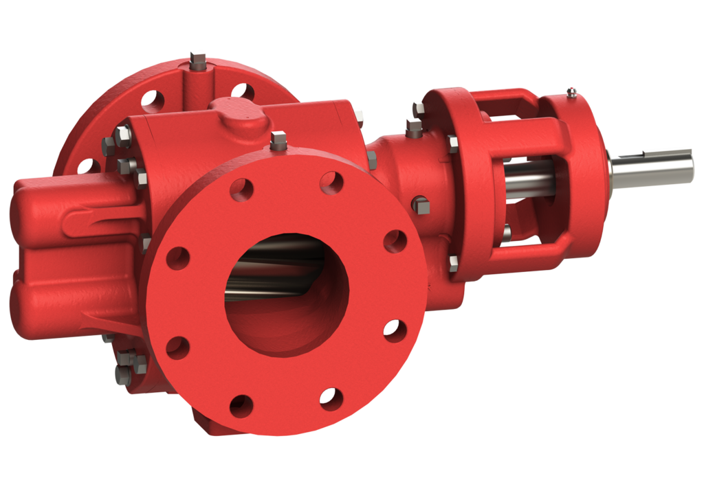
El legendario diseño de la bomba de la serie "3600" con opciones mejoradas de sellado y montaje.
La Serie Z es una bomba de engranajes helicoidales de hierro fundido que tiene una construcción de fundición y puertos de lavado/drenaje en su carcasa de sellado. Tiene una placa posterior de dos piezas para opciones de escalado flexibles, y muchas de sus piezas son intercambiables con la Serie 3600.
- Engranajes helicoidales para un funcionamiento silencioso
- Rotación bidireccional
- Opción de caja de cambios integral
- Diseño de placa posterior de dos piezas para opciones de sellado flexibles
- Flexibilidad de sellado: simple, doble o cartucho
Construcción estándar Materiales
- Carcasa de fundición estándar
- Ejes de acero endurecido
- Engranajes de acero endurecido
- Engranajes helicoidales para un funcionamiento silencioso
- Cierre mecánico sencillo
- Cojinetes de bronce resistentes al desgaste
Configuración Opciones
- válvula limitadora de presión opcional
- Revestimiento de brida para aceptar bridas ANSI
- Cierre mecánico simple, doble y de cartucho
- Cojinete exterior, en función de la disposición de la transmisión y la junta
Típico Aplicaciones
- Mezcla
- Transferencia
- Mezcla
- Recirculación
Serie Z
Excelente para mezclar, transferir, combinar y recircular una gran variedad de fluidos. Ideal para los mercados químico y petrolero
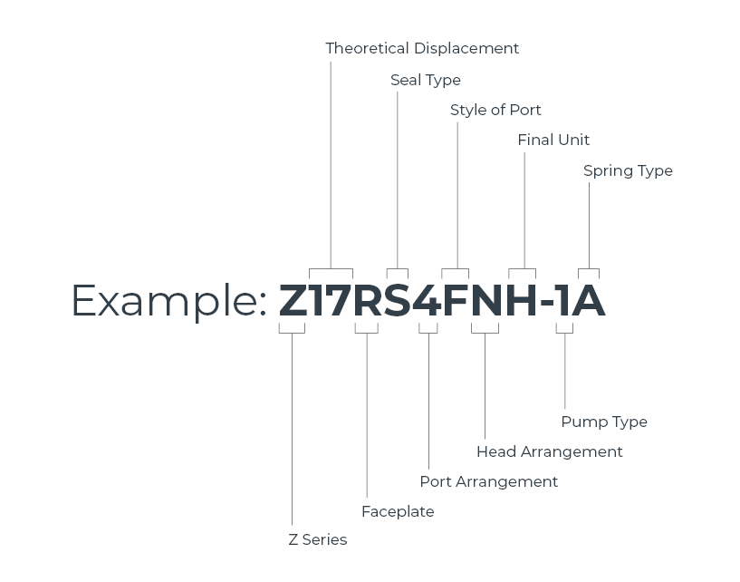
Nomenclatura de la serie Z
El número FIGURE consta de un número de nueve cifras.
El primer dígito (Z en el ejemplo) indica que se trata de una bomba de engranajes de la serie Z.
La segunda y tercera cifras (17) indican el desplazamiento teórico aproximado en galones US por 1000 revoluciones. Galones/1000 Rev. [Litros/1000 Rev.]
- 11 [41.6]
- 17 [64.4]
- 22 [83.3]
El cuarto dígito (R) indica el tipo de placa frontal de la bomba.
- P = Liso
- R = Válvula de alivio tipo RV
- E = Válvula de seguridad tipo EV
El quinto dígito (S) indica el tipo de precinto.
- S = Cierre mecánico sencillo
- D = Cierre mecánico doble
- C = Junta de cartucho
La sexta cifra (4) indica la disposición de los puertos en la caja.
- 3 = Puertos en ángulo recto
- 4 = Puertos directos
El séptimo dígito (F) indica el estilo del puerto de la caja.
- F = Brida Roper
- T = Conexiones roscadas en la carcasa
- A = Bomba con brida para aceptar bridas ANSI
La octava cifra (N) indica la disposición del cabezal de la bomba.
- N = Sin rodamiento de bolas exterior
- B = Rodamiento de bolas exterior
- O = Disposiciones de montaje auxiliares de rodamientos de bolas exteriores
La novena cifra (H) indica la unidad final.
- G = Caja de cambios construida sobre
- J = Accionamiento hidráulico directo incorporado
- H = Bomba desnuda sin accesorios
- M = Bomba montada y accesorios
Ocasionalmente, se requieren bombas o configuraciones especiales que son únicas para una aplicación concreta. Estas modificaciones se aclaran mediante un número de ESPECIFICACIÓN. La identificación de cualquier elemento diferente de una bomba estándar puede realizarse consultando a Roper Pump Company o a un distribuidor autorizado.
El número de TIPO es un número utilizado por Roper Pump Company para la identificación interna de la construcción. Incluya siempre el número de tipo en cualquier referencia a la bomba.
- A = muelle de baja presión (estándar)
- B = muelle de alta presión
El número de SERIE es un número único asignado a cada bomba construida por Roper Pump Company.
En cualquier comunicación relativa a esta bomba, Asegúrese siempre de incluir los números de figura, especificación, serie y tipo. para garantizar la correcta identificación de la bomba.
Kits de reconstrucción
Disponibles kits de reconstrucción mayores para bombas estándar. Consulte al distribuidor o al fabricante para obtener más información.
Serie Z - Tabla de tallas y especificaciones
Nota: La velocidad y el caudal máximos sólo pueden alcanzarse si las condiciones de entrada (aspiración) y del líquido son correctas. La viscosidad del líquido y la presión de descarga, además de las condiciones de bombeo, determinarán el caudal real (es decir, el teórico menos el deslizamiento).
¿Preguntas?

Z11RS3FOM-16634-1394A
Z22RS3FOM-16633-1460A
Z22RC3FOG-17795-1320A
Z22RC3FBH-17899-1B
Z17RS4AOG-5023-1460A
Z11RS4FOG-1394A
Z11PS3FBH-5023-1
Z22RS4ANH-1A
Z22RS4ABH-4763-1A
Z22RS3FOG-14925-1394A
Z22RS3FBH-9989-1A
Z22RC3FOG-17850-1460B
Z22PS4AOGLX-1320
Z17RS3FBHZ-7236-1A
Z17RC4FBH-17873-1A
Z11RC4FOG-15092-1460A
